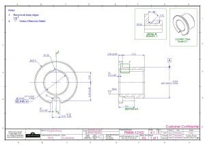
 This is the third in our series of posts where we are sharing drawings for the White Horse CAD Wobbler Engine. This week we will look at the Wobbler Engine Piston Bearing. This post is a day late because we had a few technical issues with the website.
Next week we will look at the piston sub-assembly.
Let’s look at one of the piston bearings features in a little more detail. If you would like to refer to the PDF engineering drawing it can be found by clicking here… P9999-12102_Rev1
 This bearing is a relatively simple part but there are some tight tolerances on the inside and outside diameter (H7 and f8). These tolerances are required to ensure there is sufficient clearance between mating parts. If the clearance is too small the parts may not fit together at all or there will be too much friction when the engine runs. If the clearance is too large the finished engine may be noisy and the bearings will most likely wear prematurely.
The undercut feature in Detail B often raises questions. Its purpose is to guarantee there will be no interference between mating parts. The 0.4mm radii is found on many tungsten carbide cutting inserts. However, this feature is intended to be created by using an insert with smaller radii (0.2mm) by using circular interpolation on a CNC lathe.
Carbide turning inserts are available with a range of corner radii ranging from “sharp corner” to 2.4mm. The most commonly used radii are 0.2, 0.4 and 0.8mm.
 You will notice 2 slot features in the view on the right? Both of these serve a very important purpose. The top slot feature is a lubrication channel that runs for the full length of the bearing. The bottom slot feature is an anti-rotation feature that will stop the bush spinning in the piston when it is in motion.
Don’t miss the next in the series… … sign up here…
Have a project you would like to discuss?… Contact us here…


You must be logged in to post a comment.