 This is the fourth in our series of posts where we are sharing drawings for the White Horse CAD Wobbler Engine. This week we will look at the Wobbler Engine Piston Assembly.
Next week we will look at the base, the first part of the second sub-assembly.
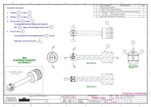
Let’s look at someone of the piston assembly features in a little more detail. If you would like to refer to the PDF engineering drawing it can be found by clicking here… P9999-12001.
 Section BB on the left shows how the two bronze bearings fit into the bearing. you will notice there is a gap between them. This is intentional. Its purpose is to provide a space for the grease. If you check back on last week’s post, you will remember the lubrication grooves on the top of the bore. The gap between the bearings is where these lubrication ways will be fed from.
 The image on the right shows how the two M4 socket set screws will stip the 2 bronze bearings from turning when the engine is running. The two screws should be tightened into the bottom of the thread to stop them from loosening.
The other component in the assembly is the O-Ring, this should be covered in a light oil before fitting to make it easier to put on. You may notice the drawing linked above has 2 sheets. This allowed us to include a large exploded isometric view to help explain how the parts fit together.
Don’t miss the next in the series… … sign up here…
Have a project you would like to discuss?… Contact us here…


You must be logged in to post a comment.