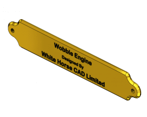
 Today’s blog is the eighth in a series of posts where we share drawings for the White Horse CAD Wobbler Engine. This week we will look at the Wobbler Engine Name Plate, which attaches to the wooden base.
Next week we will look at how all of the parts of the base fit together to form the base sub-assembly.
Let’s look at the Name Plate in a little more detail. If you would like to refer to the PDF engineering drawing, click here…P9999-13104_Rev 1
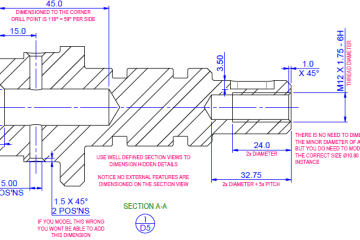
 The wobbler engine name plate is a relatively simple part. But it is likely to be something that people look at in detail. For this reason, it is essential that the text is easy to read and is centralised on the plate. On the left, you can see geometric tolerances used, in combination with drawing notes, to instruct the maker that the text is to be central about the plate length, the drawing notes also define the font and the font height.
 The image (right) details the polished surface finish on the front face of the name plate. If you read the referenced note, you will notice the method for filling the letters and polishing the front face has a detailed explanation.
The eagle eyed reader may have spotted we have made some changes to our drawing template… keep an eye out for our blog post about why we have made the changes and how we are leveraging features in SolidWorks to create clear, detailed engineering drawings.
Don’t miss the next in the series … sign up here…
Have a project you would like to discuss?… Contact us here…


You must be logged in to post a comment.