Or to put it another way… Are hand-drawn designs still relevant in the modern age? CAD

CAD System
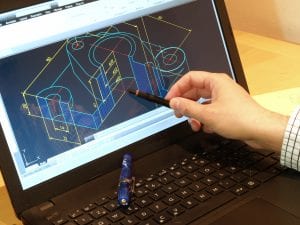
Computer Aided Design (CAD) has been around since the early 1960’s.But those early versions are a long way from what we now accept as the norm. Modern 3D Parametric CAD was first seen in 1989 but it was not widely available until the start of the millennium.
New computers, processors and operating systems have allowed CAD software to become much more commonplace in the engineering and maker communities than it was even 20 years ago. Some of the big software providers even have FREE 3D CAD software, which is, very capable. Vendors such as AutoDesk, Google, OnShape and OpenSCAD all have free or low cost options on entry level 3D CAD. Whilst these may have limited features they are all capable in their own way.

Hand Drawn Design
However, there are still a lot of designers who often start their design process using pencil and paper. Sketching out rough concepts and adding some details helps designers to consolidate ideas.
There are also several people who design complex products and geometries using nothing more than pencil and paper. These “old school” designers often have fantastic ideas. They create amazing, complex designs and drawings that are spread over many sheets of paper. The “old school” designers also have an amazing skill of turning their 3D thoughts into 2D drawings, some of which are remarkably accurate.
Unfortunately, many of the workshop skills that existed 30 or 40 years ago have been replaced by Computer Numerical Controlled (CNC) machinery. The days of presenting a full set of hand-drawn engineering drawings to a manufacturer and expecting them to produce your products cost effectively are, very sadly, coming to an end.
In today’s high-tech world, the cost-effective manufacture of even the most basic components requires a multi-axis CNC machine. While some components can be programmed manually, the coding process can be very time-consuming. For this reason, many modern engineering companies use Computer Aided Machining (CAM) software to generate cutting paths from 3D CAD models. As the reliance on CAD/CAM/CNC process increases the chances of a pencil and paper designer getting products to market without having their drawings converted into 3D CAD is becoming smaller and smaller.
This does not mean that paper and pencil designers are no longer relevant. But it does mean they need to consider another step in their design process to get their products off the drawing board. On a personal level, I think it is sad that many of the skills and processes that were around when I started my engineering career in the 1980’s are no longer considered to be “cost-effective”.

Finite Element Analysis of a hook
Transferring hand-drawn designs to CAD has a plethora of benefits. Not only can designers see their products come to life they can have them checked for manufacturability, assembly problems, interference, mechanism issues, access problems, and much more. Many CAD programs will easily output component mass for a given material, the components, assemblies centre of gravity, and many other metrics. 3D CAD models can also be used to conduct Finite Element Analyse of single components or assemblies, all from within a single piece of software.
The real power of parametric CAD comes into play when there are many iterations of components, long, short, large, small, more holes, fewer holes etc. Nearly every iteration can usually be included in a single well-constructed model file. A well-constructed model file can also be invaluable when design changes are needed, model changes are automatically reflected on the drawings.

Hand-drawn designs can be transferred to CAD files for secure storage and ease of use in manufacturing
Many people consider transferring hand-drawn designs to CAD to be cost-prohibitive. However, they seldom consider that for some components the quoting engineering company will include a hidden fee for creating 2D or 3D CAD data from drawings to aid manufacture (with absolutely no control by the original designer). This is where problems start to accumulate. Especially if more than one company is involved in production.
You may have many components, made by 3 plus manufacturers, each will create their own interpretation of the drawings in CAD. At this point, the original designer has lost control of the product. Components may not fit together properly and if a design change is needed, it is often done in isolation, and affected parts may not be updated, causing more problems later down the line.
Creating 2D and 3D CAD BEFORE you start talking to manufacturers reduces or even eliminates some of the manufacturing problems above. Each part will have its own 3D data that can be sent to the manufacturer. The manufacturer will use this 3D data in association with the 2D drawing to create the part, greatly reducing the risk of the drawings not being interpreted properly.
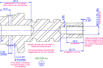
A good CAD file needs to be created with precision, forethought, and care. The files will after all most likely be used to create the cutting paths for your final products. Understanding and keeping the design intent is critical to the creation of a great set of CAD data.
Common problems include incorrectly defined geometry, features that can’t be manufactured, poorly defined drawings with over-ridden dimensions and non-constrained features. All of which can lead to “errors” during manufacturing. But of course, if the component is manufactured from the CAD and the CAD is not properly defined then the error is not fully down to manufacturing.
Good quality CAD data has the potential to save you money! Poor quality CAD data will cost you money up to 3 times…. Getting it modeled initially, then having to pay for substandard parts that are correct to the supplied CAD model, and finally having to pay for the CAD to be modified or worse, redefined from scratch.

3D render of an engine
CAD has now become mainstream, nearly every modern manufacturing company has access to at least one form of CAD or another. But that does not mean that pencil and paper designers are no longer relevant! The next high-tech component is just as likely to be designed using “old school” techniques as the latest CAD software, but in this day and age, if you want to produce cost-effective components, at some point, you are going to need to invest in CAD. Either as a service from a company such as White Horse CAD Limited, or as software from one of the many vendors available.
To find out more about our design services, please visit the White Horse CAD website.


You must be logged in to post a comment.