People often underestimate the difficulties and limitations of designing sheet metal products. Many design rules can catch the unaware design engineer off guard.
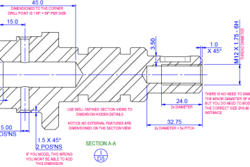
We are creating a series of practice files alongside our DFM handbook, which is intended to teach good modelling practice and the fundamental principles for manufacturing parts. The first of these lessons is a relatively simple folded plate. Whilst this looks simple, there are at least five design rules to consider. Four are mentioned in the practice document, but one is not mentioned. But if you read the sheet metal section of the DFM book, you will know what rule is missing.
When designing sheet metal products with folds, the most important thing to remember is that flat patterns are to be considered reference data unless the model uses validated manufacturing data from the company making the parts. There are other rules about hole size and the distance of features from edges and folds. All of these need to be considered when designing sheet metal products,
Sheet metal design is primarily defined by the process limitations and the tooling used by the manufacturing company. The type of tooling they use to fold parts will define the bend allowance you require, the cutting process they use may influence the shape of the part. Laser cutting will give you a lot more design freedom, but sheared or punched parts may have a more uniform finish.
Bend tooling will dictate things such as bend radius, minimum leg length and the minimum distance between bends. This is why it is critical to design sheet metal products with the guidance of the company making the parts.
If you would like more information, please contact us
or Find us on LinkedIn

You must be logged in to post a comment.