SolidWorks is the industry standard for mechanical design for a very good reason. It has some very powerful and useful features that can help experienced users create fully detailed engineering drawings for a family of products quickly and efficiently.
Designing a product using part configurations and design tables demonstrates this well. We created the model file, design table, and engineering drawing for this series of clevis pins in less than 1 hour. This simple design demonstrates the advantages of using parametric CAD data to generate and specify your parts.

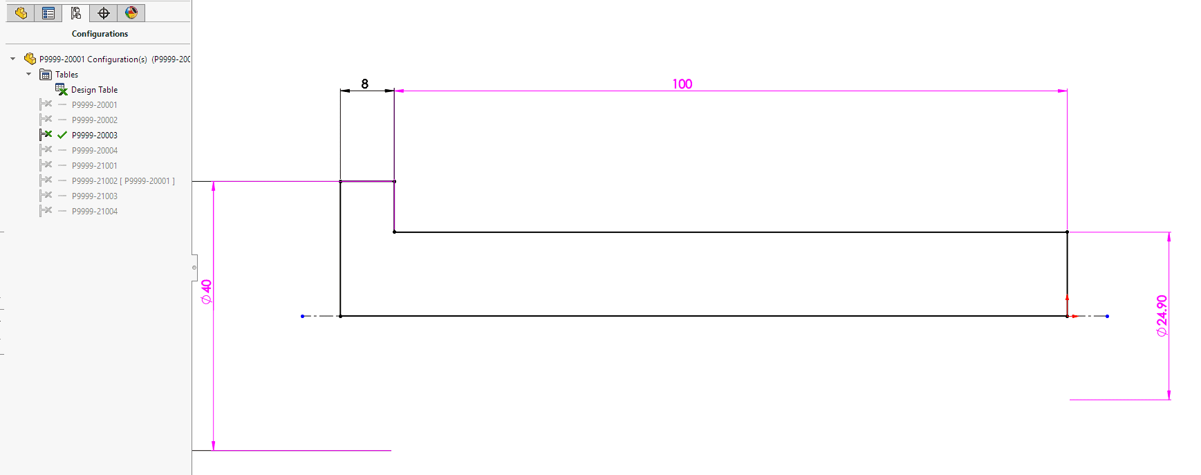
The sketch shown above controls the basic geometry of the pin. The dimensions shown in purple are controlled by the design table. The process was straightforward. We created the CAD model for the basic part and then added a configuration. The required dimensions and features were then marked as configuration specific. With this done, we created a design table. SolidWorks found the different features in our two configurations and populated an excel spreadsheet with all the required data.
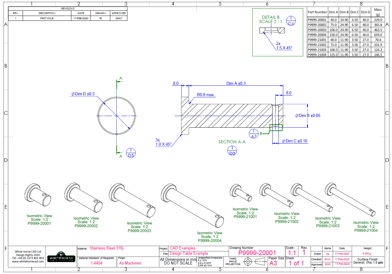
We then added six more rows to the table, entered the correct information, and configured the table so that it appears on the drawing correctly. When we rebuilt the model file, we had eight configurations of the same part. All different, this took around 30 minutes. With the model complete, we created a new drawing, added the required dimensions to the views, and then added the design table from the model file.

The drawing table and model file are now parametrically linked. If the model is updated or new part configurations are added. The drawing and its table will be updated automatically. One drawing controls many parts, with the advantage that each has its own solid model that can be used in assemblies or exported for CNC manufacture.
If you would like to hear more about how White Horse CAD can add value to your designs without adding cost sign up for our newsletter here…
Have a project you would like to discuss?… Contact us here…


You must be logged in to post a comment.