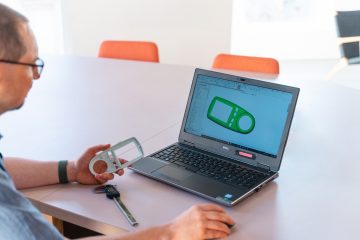
 We decided to put our new 3D scanner through its paces and chose a great challenge would be to scan and model a complex part that was originally injection moulded.
The part we scanned was the cover of a pass-through plug that measures how much electricity a socket uses.
It’s a complex part, demonstrating the scanner’s quality and our SolidWorks Skills.
 We had to scan the part several times from different angles before having enough data to go to the next stage. It was awe-inspiring to see how well the scanner software correctly orientated every scan data set to give a highly detailed, seamless set of 3D data.
3D Scanners output 3D graphical files and point clouds. These files can be 3D printed but are not solid CAD models. If you want to reproduce the part using conventional machining processes or injection moulding, the 3D scan data needs to be converted to solid CAD geometry.
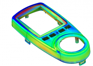
 The biggest challenge was to create accurate 3D CAD data around the point cloud data we imported from the 3D scanner. I will not bore you with the full process today, but we created most of the geometry using surface modelling before converting the surfaces to a solid body. The final results can be seen in the comparison plot on the right. The comparison plot indicates how close the final CAD model is when compared directly with the 3D scan data. In this instance, the largest error reported by SolidWorks was a little over 0.15mm. We think this was a great result for our first reverse engineering project. It demonstrates the level of accuracy that can be achieved when you combine the latest technology with 30 years of engineering expertise and 20 years of SolidWorks expertise.
If you would like to know more about our 3D scanning service or any other services, please call us on 01373 801 803 or fill in our contact form.


You must be logged in to post a comment.